Commercial Chiller

Refrigerant Leak Detection System (RLDS)

High Precision Refrigerant Monitor

RLDS

The Most Effective Refrigerant Monitor in the Industry

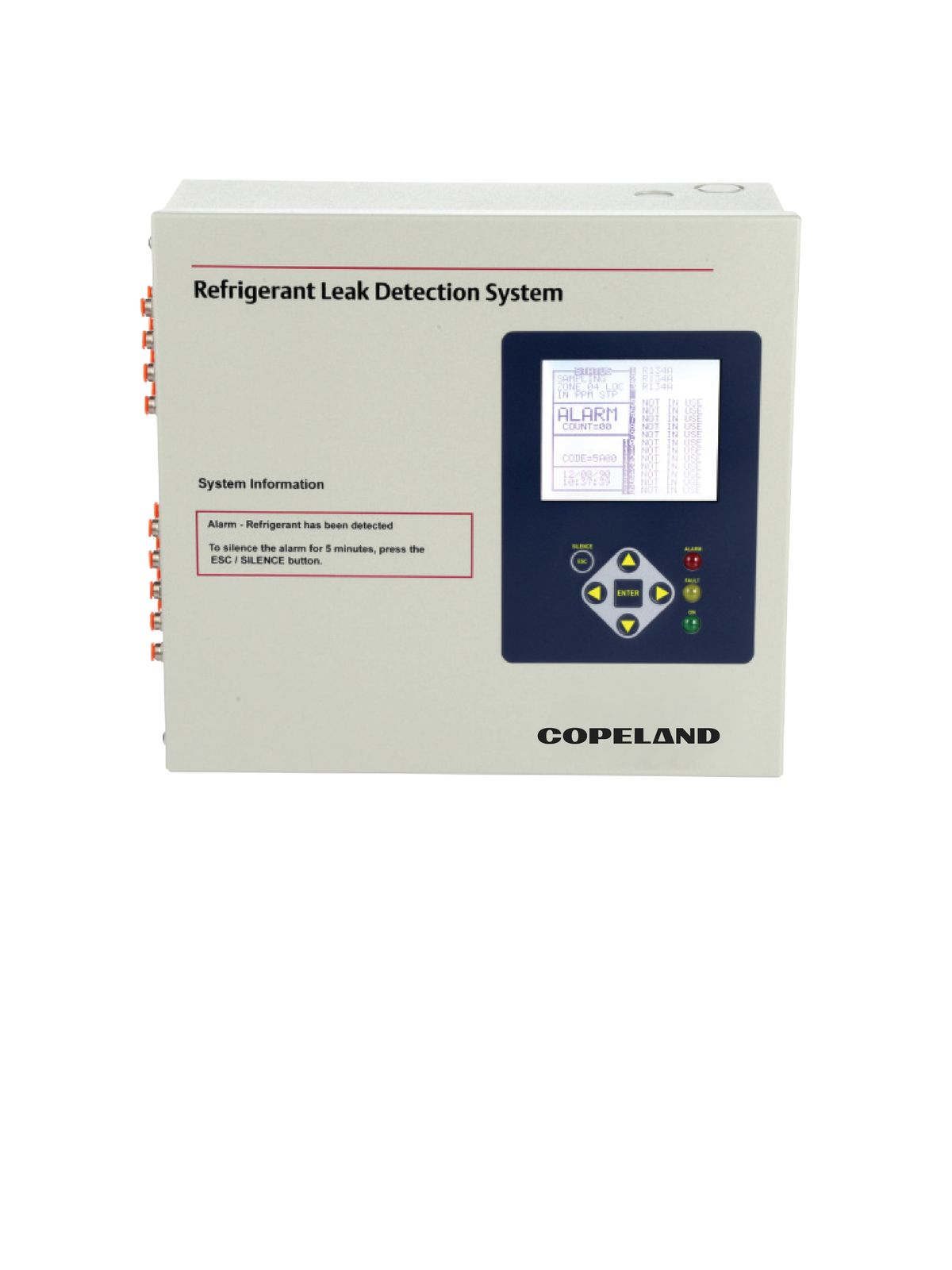
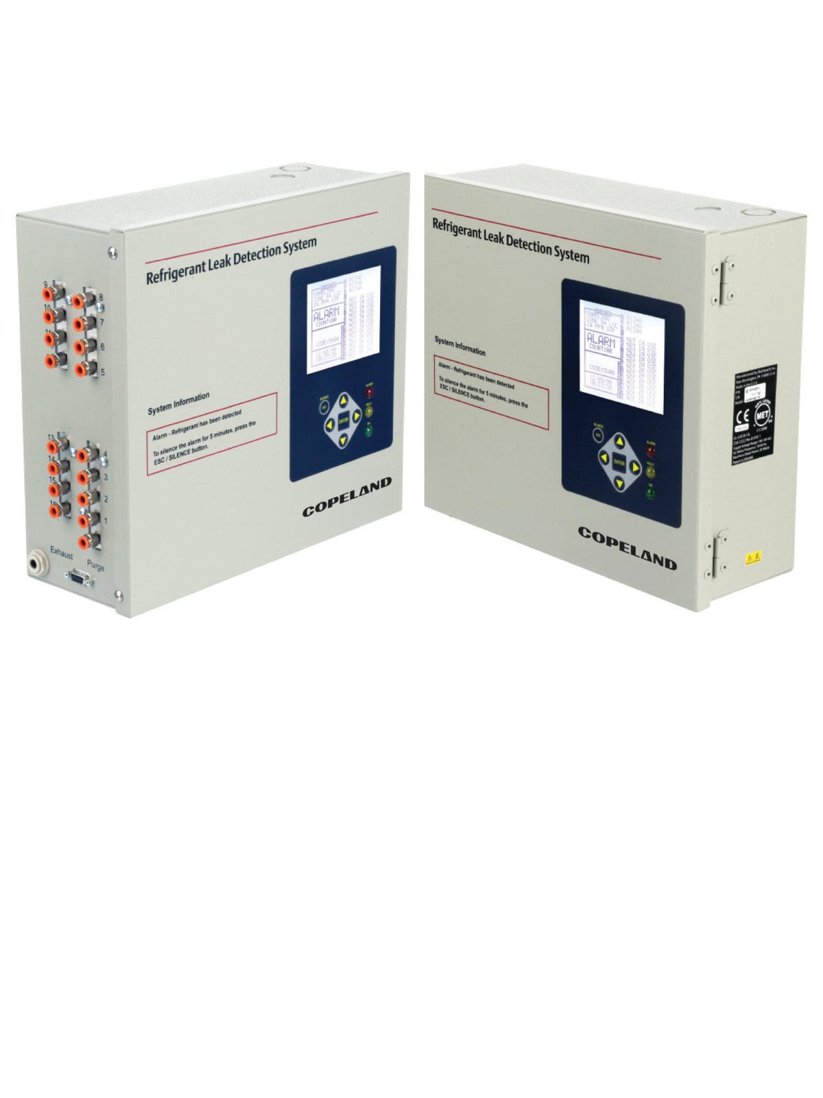
RLDS delivers the best refrigerant monitoring available, with industry-leading MDL (minimum detectable level) of 1 ppm for halogenated gases, the fastest sampling frequency and the widest range of refrigerants accurately detected. The large graphic LCD display and LED status indicators provide a system-wide overview at a glance.
RDLS3

RLDS enhances effective refrigerant management

The RLDS enhances effective refrigerant management, detecting leaks early to enable cost savings by reducing refrigerant discharge, enhancing energy effi ciency and reducing risk of refrigeration failure and product loss. A variety of communication interfaces are available, including Modbus, BACnet and LonWorks, allowing easy integration into BMS systems and remote monitoring solutions.

Technical Data

Gas Library
MEASUREMENT RLDS
UNIT CFC: R11, R12, R113, R114, R502, HFP HFC: R125, R134a, R236FA, R245Fa, R32, R404a, R407a, R407c, R-407F, R410a, R422a, R422d, R427a, R507, R508b HCFC: R123, R124, R21, R22, R227, R23, R401a, R402a, R402b, R408a, R409a, R500, R503 Halon: H1211, H1301, H2402 Other: FA188, FC72, H1234YF, H1234ZE, N1230, N7100, N7200, N7300, N7600, R424A, R426A, R438A, CUSTOM
DESCRIPTION RLDS CO2
CO2/R744
RLDS
RLDS
MEASUREMENT All gases 0 to 10,000 ppm
UNITRLDS CO2
DESCRIPTION CO2 0 to 8,000 ppm
RLDS
1 ppm MDL (most gases) +1ppm +10% of reading from 0-1,000 ppm (most gases) +1ppm +2% of reading with fi eld calibration (most gases) +10ppm +15% of reading from 0-1,000 ppm (R-11, R-21, R32)
CFC: R11, R12, R113, R114, R502, HFP HFC: R125, R134a, R236FA, R245Fa, R32, R404a, R407a, R407c, R-407F, R410a, R422a, R422d, R427a, R507, R508b HCFC: R123, R124, R21, R22, R227, R23, R401a, R402a, R402b, R408a, R409a, R500, R503 Halon: H1211, H1301, H2402 Other: FA188, FC72, H1234YF, H1234ZE, N1230, N7100, N7200, N7300, N7600, R424A, R426A, R438A, CUSTOM
MEASUREMENT RLDS CO2
UNIT+5 ppm +5% of reading from 0-1,000 ppm +10% of reading from 1,000-4,000 ppm +15% of reading from 4,000-8,000 ppm
DESCRIPTION RLDS
+0.8% (R134a) of reading per OC between purge cycles
MEASUREMENT CFC: R11, R12, R113, R114, R502, HFP HFC: R125, R134a, R236FA, R245Fa, R32, R404a, R407a, R407c, R-407F, R410a, R422a, R422d, R427a, R507, R508b HCFC: R123, R124, R21, R22, R227, R23, R401a, R402a, R402b, R408a, R409a, R500, R503 Halon: H1211, H1301, H2402 Other: FA188, FC72, H1234YF, H1234ZE, N1230, N7100, N7200, N7300, N7600, R424A, R426A, R438A, CUSTOM
UNITRLDS CO2
DESCRIPTION CO2/R744
RLDS
All gases 0 to 10,000 ppm
MEASUREMENT RLDS CO2
RLDS CO2
UNITCO2 0 to 8,000 ppm
DESCRIPTION RLDS
1 ppm MDL (most gases) +1ppm +10% of reading from 0-1,000 ppm (most gases) +1ppm +2% of reading with fi eld calibration (most gases) +10ppm +15% of reading from 0-1,000 ppm (R-11, R-21, R32)
RLDS CO2
MEASUREMENT +5 ppm +5% of reading from 0-1,000 ppm +10% of reading from 1,000-4,000 ppm +15% of reading from 4,000-8,000 ppm
CO2/R744
Measuring Range
RLDS
All gases 0 to 10,000 ppm
RLDS CO2
CO2 0 to 8,000 ppm
Accuracy
RLDS
1 ppm MDL (most gases) +1ppm +10% of reading from 0-1,000 ppm (most gases) +1ppm +2% of reading with fi eld calibration (most gases) +10ppm +15% of reading from 0-1,000 ppm (R-11, R-21, R32)
RLDS CO2
+5 ppm +5% of reading from 0-1,000 ppm +10% of reading from 1,000-4,000 ppm +15% of reading from 4,000-8,000 ppm
Temperature Drift
RLDS
+0.8% (R134a) of reading per OC between purge cycles

Technical Specifications

Coverage
SPECIFICATION Zones: 4,8,12 and 16 zone systems available
DESCRIPTIONProprietary non-dispersive infrared (NDIR) technology
12.23”H x 13.7” x 4.96 (21.0642 cm x 34.7980 cm x 12.5984 cm)
15 lbs (6.8 kg)
Front Panel with 3 Indicator Lights: • Green = Monitor is powered on. LED glows during normal operation; fl ashes when unit is in warm-up mode • Red = Alarm. LED fl ashes when any point has exceeded the alarm setting • Yellow = Fault. LED fl ashes when there is a system fault
Zones: 4,8,12 and 16 zone systems available
SPECIFICATION Full two-way communication with BMS via RS-485 serial interface. RS-232C communication port standard.
DESCRIPTIONFour SPDT alarm contacts are provided rated 2A at 250 VAC (inductive), 5A at 250 VAC (resistive).Three assigned to ppm level alarms, one assigned to system faults.
Optional dual 4-20mA DC isolated outputs. Channel 1 = zone area, Channel 2 = ppm
Less than 40dB(A) @ 10 feet (3 meters)
5 to 315 seconds – depending on air line length and number of zones
Sensor
SPECIFICATION Automatic or manual (hold)
DESCRIPTION1200 ft max (500 ft for NH3) for combined length of sample and exhaust tubing (each zone)
Fully automatic system reset. All programmed parameters retained.
32°F to 122°F (0°C to 50°C)
5% to 90% RH non-condensing
Proprietary non-dispersive infrared (NDIR) technology
SPECIFICATION 6,562 ft (2,000 m)
DESCRIPTION100 to 240 VAC, 50/60 Hz, 20W
UL 61010-14, CAN/CA 22.2 No. 61010-1; EN61010-1, EN61326; EN14624; CE Mark
SPECIFICATION Proprietary non-dispersive infrared (NDIR) technology
DESCRIPTION12.23”H x 13.7” x 4.96 (21.0642 cm x 34.7980 cm x 12.5984 cm)
Dimensions
15 lbs (6.8 kg)
Front Panel with 3 Indicator Lights: • Green = Monitor is powered on. LED glows during normal operation; fl ashes when unit is in warm-up mode • Red = Alarm. LED fl ashes when any point has exceeded the alarm setting • Yellow = Fault. LED fl ashes when there is a system fault
Full two-way communication with BMS via RS-485 serial interface. RS-232C communication port standard.
SPECIFICATION Four SPDT alarm contacts are provided rated 2A at 250 VAC (inductive), 5A at 250 VAC (resistive).Three assigned to ppm level alarms, one assigned to system faults.
DESCRIPTIONOptional dual 4-20mA DC isolated outputs. Channel 1 = zone area, Channel 2 = ppm
12.23”H x 13.7” x 4.96 (21.0642 cm x 34.7980 cm x 12.5984 cm)
Weight
15 lbs (6.8 kg)
User Interface
Front Panel with 3 Indicator Lights: • Green = Monitor is powered on. LED glows during normal operation; fl ashes when unit is in warm-up mode • Red = Alarm. LED fl ashes when any point has exceeded the alarm setting • Yellow = Fault. LED fl ashes when there is a system fault
Communications
Full two-way communication with BMS via RS-485 serial interface. RS-232C communication port standard.
Alarms
Four SPDT alarm contacts are provided rated 2A at 250 VAC (inductive), 5A at 250 VAC (resistive).Three assigned to ppm level alarms, one assigned to system faults.
Conditioned Signal
Optional dual 4-20mA DC isolated outputs. Channel 1 = zone area, Channel 2 = ppm
System Noise
Less than 40dB(A) @ 10 feet (3 meters)
Response Time
5 to 315 seconds – depending on air line length and number of zones
Sampling Mode
Automatic or manual (hold)
Monitoring Distance
1200 ft max (500 ft for NH3) for combined length of sample and exhaust tubing (each zone)
Power Safety Mode
Fully automatic system reset. All programmed parameters retained.
Operating Temperature
32°F to 122°F (0°C to 50°C)
Ambient Humidity
5% to 90% RH non-condensing
Altitude Limit
6,562 ft (2,000 m)
Power
100 to 240 VAC, 50/60 Hz, 20W
Approvals
UL 61010-14, CAN/CA 22.2 No. 61010-1; EN61010-1, EN61326; EN14624; CE Mark

Order Information

808-2004
PART # RLDS 4 Zone
DESCRIPTIONRLDS 4 Zone, w/HHT & Gateway
RLDS 8 Zone
RLDS 8 Zone, w/HHT & Gateway
RLDS 12 Zone
RLDS 4 Zone
PART # RLDS 12 Zone, w/HHT & Gateway
DESCRIPTIONRLDS 16 Zone
RLDS 16 Zone, w/HHT & Gateway
RLDS CO2 4 Zone
RLDS CO2 4 Zone, w/HHT & Gateway
808-2005
PART # RLDS CO2 8 Zone
DESCRIPTIONRLDS CO2 8 Zone, w/HHT & Gateway
RLDS CO2 12 Zone
RLDS CO2 12 Zone, w/HHT & Gateway
RLDS CO2 16 Zone
RLDS 4 Zone, w/HHT & Gateway
PART # RLDS CO2 16 Zone, w/HHT & Gateway
PART # RLDS 4 Zone, w/HHT & Gateway
DESCRIPTIONRLDS 8 Zone
RLDS 8 Zone, w/HHT & Gateway
RLDS 12 Zone
808-2008
RLDS 12 Zone, w/HHT & Gateway
PART # RLDS 16 Zone
DESCRIPTIONRLDS 16 Zone, w/HHT & Gateway
RLDS CO2 4 Zone
RLDS CO2 4 Zone, w/HHT & Gateway
RLDS 8 Zone
808-2009
RLDS 8 Zone, w/HHT & Gateway
808-2012
RLDS 12 Zone
808-2013
RLDS 12 Zone, w/HHT & Gateway
808-2016
RLDS 16 Zone
808-2017
RLDS 16 Zone, w/HHT & Gateway
808-2104
RLDS CO2 4 Zone
808-2105
RLDS CO2 4 Zone, w/HHT & Gateway
808-2108
RLDS CO2 8 Zone
808-2109
RLDS CO2 8 Zone, w/HHT & Gateway
808-2112
RLDS CO2 12 Zone
808-2113
RLDS CO2 12 Zone, w/HHT & Gateway
808-2116
RLDS CO2 16 Zone
808-2117
RLDS CO2 16 Zone, w/HHT & Gateway