CO₂ (R-744) is a natural refrigerant with a global warming potential (GWP) of 1 and zero ozone depletion potential (ODP), making it one of the most promising alternatives to high-GWP hydrofluorocarbon (HFC) systems for commercial food retail.
As U.S. adoption accelerates, understanding the characteristics, applications and servicing requirements of CO₂ refrigeration technology is essential for supermarket owners, operators and technicians.
For more than a decade, Copeland has been developing integrated compression technologies, controls and components to help facilitate the use of CO₂ refrigeration in U.S. markets. That commitment continues today through ongoing research and development (R&D) and partnerships with leading equipment manufacturers and end users making the transition to CO₂. This article, combined with the CO₂ Chats video series, is designed to provide the foundational understanding needed to navigate that transition with confidence.
What are the unique properties of R-744?
R-744 has distinct thermo-physical properties that set it apart from legacy HFC refrigerants. These properties directly influence system design, operating procedures and service requirements.
Low critical point
R-744 has a low critical point of 87.8°F. When ambient temperatures rise above approximately 75°F, system conditions cause the refrigerant to enter the gas cooler as a supercritical fluid. In this state, pressure and temperature relationships rise and fall independently of each other. Below 87.8°F, R-744 operates in subcritical mode. Above it, the system enters transcritical mode.
High operating pressures
CO₂ system operating pressures are significantly higher than those of traditional HFC systems such as R-404A or R-410A. On a 95°F summer day, medium-temperature (MT) compressor discharge pressures can reach 1,400 psi. MT discharge lines are constructed with stainless steel or special ferrous alloy copper to handle these pressures.
Within a facility, a high-pressure expansion valve reduces refrigerant pressure from the gas cooler to approximately 550 psi before transferring it to a flash tank. Liquid refrigerant exits at the bottom of the flash tank at 40°F (550 psi) and feeds MT evaporators operating at approximately 22°F (420 psi) and low-temperature (LT) evaporators operating near -20°F at a lower pressure of 200 psi. Proper training and tooling can mitigate reservations about CO₂'s high pressures.
High triple point
R-744 has a high triple point at which gas, liquid and solid states coexist, occurring at -69.8°F and 60.4 psi. Although -69.8°F is well below normal operating ranges, the hyper-reactivity of a CO₂ system can cause pressure to reach 60.4 psi or lower. When this occurs due to improper maintenance, R-744 turns into dry ice, stops refrigerant flow and causes a range of potential problems.
High density
Because R-744 has a higher density than typical HFC refrigerants, CO₂ refrigeration technology requires smaller compressor displacements, although the motor is sized similarly to carry the workload. Smaller pipe diameters can be used, especially on the suction side. Due to high operating pressures, all system components must be rated for a higher maximum working pressure.
What are the best practices for servicing CO₂ refrigeration systems?
Technicians servicing CO₂ transcritical booster systems should understand key handling, charging and safety procedures before beginning any work.
Storing CO₂
R-744 tank storage and refrigerant cylinder best practices are similar to those of legacy HFCs, including stacking procedures, safety precautions and designated storage areas. However, CO₂ tanks are reinforced to handle high pressures and weigh significantly more. Empty CO₂ tanks can weigh close to 123 lbs. and reach nearly 180 lbs. when fully charged.
Supermarkets that prefer to maintain an entire system charge in reserve could potentially require 2,000 lbs. of refrigerant. Storing that volume would require 40 cylinders weighing 7,200 lbs. (3.6 tons). Contractors need to understand where to store reserve refrigerant and whether the volume and weight could affect building codes or a building's structural integrity.
Charging a CO₂ refrigeration system
The most important consideration when charging a CO₂ system is guarding against the refrigerant's triple point pressure (60.4 psi) to prevent the formation of dry ice. When the system is below 60.4 psi, technicians should charge with vapor until the system reaches CO₂’s triple point or at least 100 psi. After achieving 100 psi, technicians can switch to liquid charging to speed up the process.

Failure to follow this procedure is likely to result in dry ice formation in the charging line, a common and potentially costly mistake for those unfamiliar with CO₂ installations.
Dealing with trapped liquid
Because CO₂'s coefficient of expansion (COE) is higher than that of a typical HFC refrigerant, refrigerant pressure can increase rapidly between two valves. Pressure can increase 145 psi for every 1.8°F rise in temperature. Sections of a system must be fitted with appropriate check valves or pressure-relief valves for safe operation and service.
Detecting leaks in CO₂ systems
R-744 is colorless, odorless and heavier than air, making leak detection a critical safety requirement. CO₂ transcritical booster systems must utilize integrated leak detection systems with detection devices mounted 18 inches off the ground. Copeland has designed CO₂-specific leak detection technology that can quickly sense elevated CO₂ levels in a machine room or walk-in box.
Copeland offers both a standalone CO₂ leak detection solution and devices that integrate seamlessly into a building management system (BMS), such as the Copeland supervisory control platform.
Safe handling best practices
Technicians should take proper precautions when handling high-pressure CO₂ refrigeration systems. Even when a system is shut off, standstill pressures remain high. Because CO₂ is heavier than air, it can quickly displace oxygen when released in excessive amounts. CO₂ vapor temperature at atmospheric pressure is -109.3°F. Technicians should avoid handling it in confined spaces, use proper leak detection procedures and equipment, follow proper service procedures, and always wear personal protective equipment (PPE) to limit the risk of skin burns. With proper training, tools and equipment design, CO₂ is a safe and natural refrigerant alternative.

How does a CO₂ transcritical booster system operate?
A CO₂ transcritical booster system is designed to transition between subcritical and transcritical modes, with advanced electronic controls managing nearly all aspects of operation.
The difference between subcritical and transcritical modes
When R-744 is at saturation and below 87.8°F, the system operates in subcritical mode. Above this temperature, R-744 is no longer at saturation and the system enters transcritical mode. Unlike traditional HFC systems, which have much higher critical points, CO₂ systems can operate in transcritical mode for extended periods during a typical year.
Managing high system pressures
R-744 reacts quickly to changes in pressures and temperatures, making it critical to establish a stable baseline performance during commissioning. Technicians should focus on the configurations of the gas cooler, high-pressure valve and flash tank by:
- Controlling variable fan speeds
- Modulating the high-pressure valve
- Modulating the bypass gas valve
- Maintaining consistent flash tank pressure
- Assuring smooth compressor staging
Since all these aspects are managed by electronic controls, technicians must interface with these controls to bring key system components into equilibrium.
Preserving CO₂ system charge during a shutdown
Power outages and system shutdowns can have significant impacts on a CO₂ transcritical booster system. CO₂ transcritical booster systems are designed with pressure-relief valves in each zone to allow for the safe release of refrigerant during extended shutdowns. During brief shutdowns, a system's thermal inertia from its flash tank, liquid line and MT and LT evaporators will sustain proper pressures for a significant period.
An auxiliary condensing unit powered by a backup generator can also help keep pressures in check during an extended power outage. The condensing unit typically utilizes a dedicated heat exchanger connected to the system's flash tank or receiver. When the system is powered down, warm gas naturally migrates through the cold heat exchanger, condenses into liquid and returns to the flash tank at a lower temperature and saturation pressure, helping to prevent refrigerant loss through pressure-relief valves.
Preventing flooded evaporators during a power outage
CO₂ transcritical booster systems incorporate specific strategies to prevent evaporator flooding during a power outage:
- Stepper-motor EEV systems: A solenoid valve at the inlet of the electronic expansion valve (EEV) can be set to close upon loss of power, preventing evaporator flooding.
- Battery backup: A battery backup on the case control can shut off refrigerant flow when necessary.
- Pulse-width modulated (PWM) valves: These are designed to automatically close to prevent liquid from flooding the evaporator and protect the compressor when power is restored.
Before a system is brought back online, service contractors should make sure they clearly understand how the valves in each system will operate and/or close and confirm that all floodback mitigation strategies have worked as expected.
What are the leading CO₂ system design strategies?
System designers have developed two primary CO₂ refrigeration architectures that differ significantly from traditional HFC-based systems.
CO₂ transcritical booster system
MT compressors discharge into a gas cooler typically located on the roof of a facility, where system pressures can reach 1,400 psi on a hot summer day. Refrigerant is circulated back into the building through a high-pressure valve, which drops pressure to approximately 550 psi and deposits a refrigerant mixture into the flash tank at 40°F equivalent saturation.

The system circulates 40°F liquid through insulated liquid lines to feed MT and LT cases. LT compressors discharge into the MT compressors, allowing the MT compressors to boost the refrigerant to the gas cooler. This is why it is referred to as a booster system. The MT compressors are fed by three sources:
- The total heat of rejection from LT compressors
- MT suction from the evaporators
- Excess flash gas via the bypass line
CO₂ cascade system
A CO₂ cascade system offers an alternative for retailers who want a low-GWP option without a full transcritical booster system. The high (MT) and low (LT) stages are completely independent of each other, connected only by a single heat exchanger. The high stage typically uses a lower-GWP, medium-pressure HFC refrigerant such as R-513A, while the low stage uses CO₂ for LT loads. With a GWP of 1, this cascade architecture can meet many retailers' sustainability objectives.
Leveraging heat reclaim
CO₂ systems are excellent candidates for heat reclamation, whether for heated air, hot water or heating slabs beneath freezers. Many retailers capitalize on this opportunity to lower emissions and reduce reliance on fossil fuels. In addition, the liquid quality of R-744 is not affected when head pressures are raised to generate more heating capacity. The flash tank or receiver is designed to keep refrigerant at a consistent pressure even while head pressures fluctuate during transcritical operation.
How is energy efficiency optimized in CO₂ transcritical systems?
When R-744 exceeds its critical point of 87.8 °F, the refrigerant enters a supercritical phase where the relationship between pressure and temperature becomes uncoupled. To optimize the coefficient of performance (COP) in a CO₂ transcritical booster system, we must understand the function of the gas cooler and the characteristics of R-744 as it enters this supercritical zone.

Below the critical point, the gas cooler acts like a condenser. Thus, R-744 exists in a predictable state of saturation — if you know the pressure, you can determine the temperature (and vice versa). In its subcritical state, the high-pressure control algorithm automates system pressures according to a specified sub-cooling setpoint.
Above 87.8 °F, the pressure can change without having an impact on the temperature (and vice versa). System designers can take advantage of this phenomenon when optimizing COP. When operating transcritical mode, the high-pressure control always seeks to maintain an optimal pressure setting for each gas cooler outlet temperature. Today’s sophisticated high-pressure controls are continually adjusting gas cooler outlet pressures in transcritical mode to produce the most optimal BTU/W option.
How are energy efficiencies maintained in warm climates?
Energy efficiency in a CO₂ transcritical booster system depends on ambient temperature range, regional humidity, water availability and cost, and peak demand charges. Leading optimization strategies include:
- Adiabatic gas cooler
- Parallel compression
- Mechanical sub-cooling
- Gas ejector
- Zero superheat control of MT evaporators (annualized benefit)
- Liquid ejector (annualized benefit)
Adiabatic gas cooler
An adiabatic gas cooler uses wetted pre-cooling pads outside the condenser coils to delay the system from entering transcritical mode. When ambient temperature reaches approximately 72°F, a water solenoid is energized, causing water to be sprayed along the top of the adiabatic pads. As the water trickles down the pads, a condenser pulls air through these wetted pads, causing cooler, moist air to hit the condenser coils. This drops temperature and pressure, improving energy efficiency by allowing the system to operate at lower pressures.
Parallel compression
Parallel compression refers to adding a separate suction group that compresses excess flash gas and circulates it directly to the gas cooler instead of circulating from the flash tank to the MT suction as in a standard transcritical booster system. This allows the parallel compressor to operate at approximately 550 psi suction pressure rather than the MT suction pressure of 420 psi. The higher suction pressure yields greater compressor capacity with less effort, reducing the heat of compression and overall energy consumption. When annualized in a typical environment, parallel compression can potentially save up to 10% in energy costs.
CO₂ controls and compression technologies from Copeland
Copeland offers a comprehensive suite of CO₂-approved controls, compression technologies and system components:
Supervisory controls
- E3 supervisory control for CO₂ applications, with native CO₂ applications for start-up, commissioning and service
- CO₂ refrigeration monitoring and controls
- Heating, ventilation, and air conditioning (heating, ventilation and air conditioning (HVAC) and lighting controls
- Remote access, automated alerts and mobile-ready interface

High-pressure CO₂ controls
- High-pressure and bypass valve control
- Gas cooler outlet pressure and temperature controls
- Flash tank pressure control
Case controls
- XM600 series controls
- Copeland CC200 case controller
- Pulse-width modulation (PWM) valves
- Stepper-motor electronic expansion valves (EEVs)
- Remote display access

Drives
- Copeland EVM variable frequency drives (VFDs): 1/2 to 30 HP
- Copeland EVH VFDs: 1 to 250 HP
- Wide range of connectivity options, including Bluetooth® within the EVM series
- Onboard compressor protection
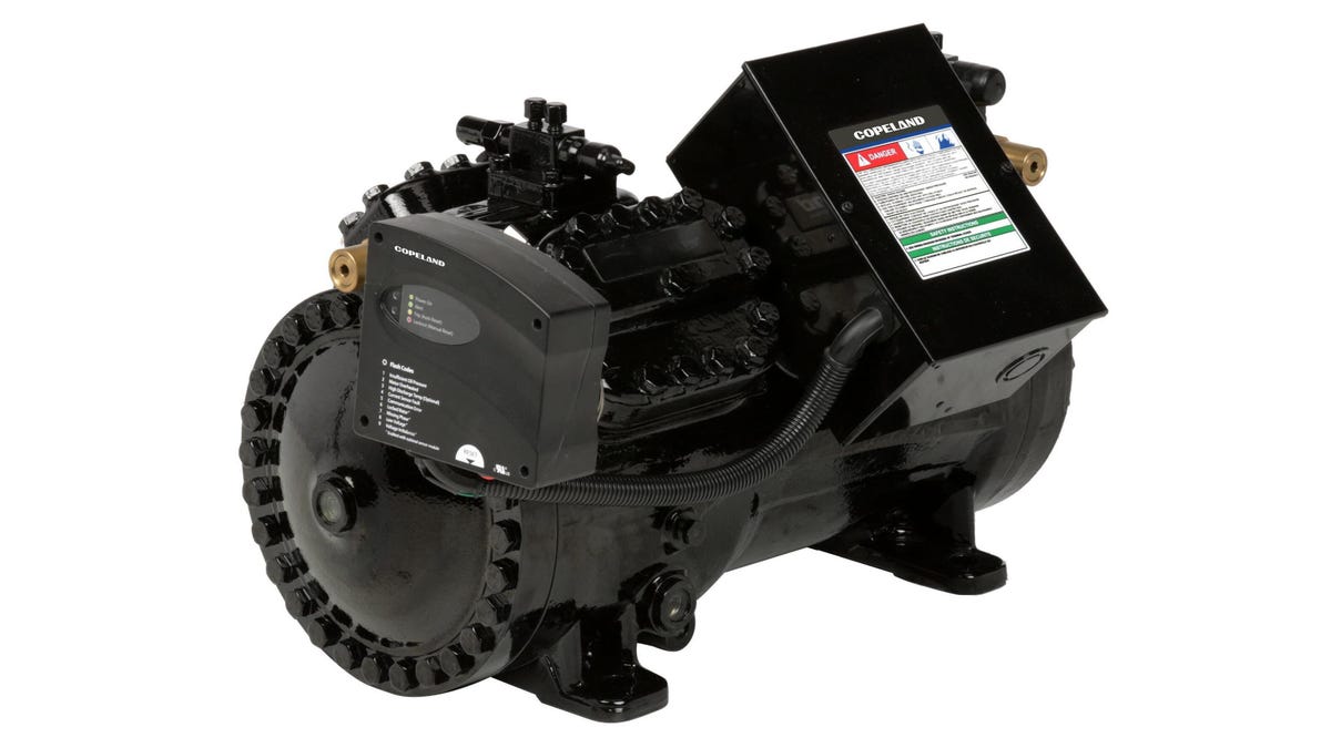
Transcritical semi-hermetic compressors
- 9 displacements with onboard diagnostics
- Capacity range from 17.5 to 354 MBH at 20°F evaporating, 95°F gas cooler outlet at 60 Hz
- Rated for variable-speed drive inputs (25 to 70 Hz and 30 to 70 Hz depending on model)
- Ideal for parallel compression configurations
Subcritical semi-hermetic compressors
- 3 displacements with onboard diagnostics
- Capacity range from 33 to 179 MBH at -25°F evaporating, 20°F saturated discharge temperature at 60 Hz
- Rated for variable-speed drive inputs: 25 to 70 Hz
Subcritical scroll compressors
- 6 displacements
- Capacity range from 4 to 104 MBH at -25°F evaporating, 20°F saturated discharge temperature at 60 Hz
- 3 digital displacements providing 10 to 100% capacity modulation
CO₂-approved system components
- Oil management
- High-pressure and bypass valves
- Optical level sensors
- Pressure switches
- Temperature and pressure sensors
- Leak detection
Frequently asked questions about CO₂ refrigeration technology
Q: What is the difference between CO₂ refrigeration and traditional HFC refrigeration?
CO₂ refrigeration (R-744) operates at significantly higher pressures than HFC systems such as R-404A or R-410A, and has a much lower critical point of 87.8°F. This means CO₂ systems regularly enter transcritical mode during warm weather, requiring specialized controls, components and servicing procedures not needed in traditional HFC systems.
Q: Why is CO₂ considered a sustainable refrigerant option?
R-744 has a GWP of 1 and zero ODP, making it one of the most environmentally favorable refrigerants available. As regulations increasingly restrict high-GWP HFC refrigerants, CO₂ refrigeration technology enables food retailers to reduce their environmental impact and comply with evolving standards.
Q: What is transcritical mode in a CO₂ system?
Transcritical mode occurs when R-744 exceeds its critical point of 87.8°F. Above this temperature, the refrigerant enters a supercritical phase in which pressure and temperature are no longer directly coupled. Unlike HFC systems, CO₂ transcritical booster systems are specifically designed to manage this operating mode through advanced high-pressure controls and gas cooler configurations.
Q: How do CO₂ systems perform in warm climates?
CO₂ transcritical booster systems can maintain strong energy performance in warm climates through targeted optimization strategies such as adiabatic gas cooling, parallel compression, mechanical sub-cooling and gas ejectors. Retailers should work with equipment suppliers and design engineers to specify the right combination of strategies based on regional climate conditions and energy costs.
Q: Is CO₂ safe to handle as a refrigerant?
CO₂ is safe to handle when proper protocols are followed. Because R-744 is heavier than air and can displace oxygen in confined spaces, CO₂ transcritical booster systems require integrated leak detection. Technicians must use appropriate PPE, follow proper service procedures and avoid working with CO₂ in confined spaces without adequate ventilation and detection equipment.